페이지

Power Amplifier (A, B , AB class) with LT spice - B amplifier

B class Amplifier (push-pull 라고 불리기도): npn ( FET에서 source follower), pnp( FET 에서 source follower) 로 구성

우선 BJT (2N3904, 2N3906)로 amplifier 구성
B class amplifier는 DC bias current가 항상 공급되는 것은 아니고 입력이 각각의 npn or pnp transistor turn on 될 때만 전력 소모가 되는 장점이 있다

이 amplifier 구성이 source follower 로 구성 되기에 우리는 voltage buffer이해해야 함. 따라서 입력 신호를 10mVpp와 같은 작은 voltage를 가진 신호를 입력으로 구성 하면 본인이 기대한 output 출력을 보기 힘들다. 따라서 large signal behavior를 보기위해 10Vpp를 입력으로 구성을 해 볼 것이다.

 기본 구성
1. collector pin 가 output pin 이 될 것이고 
2. 12V (transistor 따라 맞게 선택하면 됨)
3. 입력 sine 파는 10Vpp


결과에서 보이듯이 입력(Vin) 대비 출력파(Vload)를 transient waveform을 볼 예정이다. 
voltage
current

Power


Power Amplifier (A, B , AB class) with LT spice - A amplifier

A class Amplifier

우선 BJT (2N3904)로 amplifier 구성
A class amplifier는 DC bias 계속 공급 되고 그런 상황에서 시그널이 증폭하는 amplifier를 A class amplifier로 부른다.
 기본 구성
1. collector pin 이 output pin 이 될 것이고
2. 12V (transistor 따라 맞게 선택하면 됨)
3. 입력 sine 파는 10mVpp

결과에서 보이듯이 입력(Vin) 대비 출력파(Vload)를 transient waveform을 볼 예정이다.


결과
입력 10mV대비 ~12.5mV정도 output sine wave를 얻었기에 voltage amplifying 성공


* Vpp: peak-peak voltage를 의미


계획 - solar system 만들기

계획

1. 최종 목표:  옥상에 상용화 되어 있는 solar panel을 직접 만들어 보는 것 (*grid power system 구현)
2. 중간 목표: 작은 *off-grid power system 에 해당하는 것을 구현 한 후
    최종 목표를 향해 달려 가는 것


  - 세부내용:
         
다음과 같이 off-grid system을 구현 할 예정입니다.
하나하나 작업을 해야 하므로( 회사를 다니며),
현재 계획은 Charge Controller 를 직접 만들어 보는 것으로 시작 할 예정이다.
왜냐 하면 나머지는 부분들, 예를 들어 solar panel, battery 등은 다음의 나오는 질문을 해결 한 후 구매 하면 되기 때문이다.

Off Grid Solar Power - How to Calculate Your Needs


- 현재 태양열 panel을 고정하는 (일종의 mechanical parts) 물품을 구매하는 것도 추후에 어려운 일 중 하나라고 생각이 든다( 구매)

아래 홈페이지에서 하면 될 듯 싶다.
http://www.renogy.com/


*off-grid power system
여기서 잠깐: off-grid power system 이란?
  --> local utility company's system에 연결 하지 않고 그냥 자체 시스템으로 연결 하는 시스템, 즉 한전의 전력망과 연결 하지 않으면 off-grid system인 것이고 연결하면 on-grid system(or grid system)인 것이다.
 예를 solar panel을 스마트 폰 충전 하려 만드다면 이건 off-grid system을 구현 한다고 보면 될 거 같다.


*solar panel: 태양에너지를 전기 에너지로 바꾸어 주는 것)

Replace a fuse of LED TV

JVC 40" Class Model No : EM40NF5


Before repairing any electrical products, even though you would know how to read electrical circuits, I would recommend to get helps from a customer center of a product you have in your country.
Once you open or disassemble your product, you would not get any free support from the customer center even though the warranty is valid. ( I think I read the contents in a manual document of the product but to be sure, you may want to check if it is true or not). 


I bought the JVC 40" LED TV at COSCO U.S. when I was there and I brought it to my home town to give my mother.

For the first time, the TV was turned on and my mother could watch the TV. ( My mother have already had SetTop box - without it , you guys may not watch TV program through the TV).

I thought the TV is available for both 110 and 220 AC voltage but maybe second and third time after, she found the TV was not turned on anymore.
when I heard, I realized I did not check what voltage on the TV is available.

After that, I tried to get a service from a JVC service center but what I found is the product in Korea is not available for them to provide a service to a customer because they don't deal with JVC TV in Korea. At the same time, i tried to get any helps through JVC website but I could not get any helps, so I gave up to get any helps from the company.

At that time, there are 3 options in my hands
1. Throw it away
2. Check if it is refundable from COSCO Korea
3. fix it by myself.

I have decided to fix it after deliberation


To fix the TV,

I need to dissemble the TV , I thought it is easy for the first time but it was not.

Here is what I did.

1. I got all screw drivers out from the TV 
2. I tried to open the back cover ( the plastic back cover of the TV , back of the display)
   - here is what I found 
        a. Try to open the cover by putting a bar or something similar into a hole and widening the gap between the cover and panel until the gap is slightly wider.

         b. Go to the side of the TV (you can start the left side) to open the gap to make it wider and go to the remainder. 

3. After you disassemble it, you can see the circuit of power supply and others. 
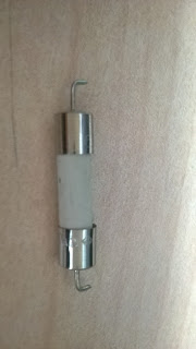
4. Check if the power supply fuse is ok or not ( I found the fuse of power supply was burned.) The fuse shown below is the burned fuse I cut from the TV.

The picture does not show us clearly what kind of fuse is used in the TV but if we take a look at the metal part, we can find T4.0H250V 
Also, the fuse is used with wire Leads, I guess I should not cut the leads like being shown in the picture but should cut it all at the end of metal (no leads -  the leads will be acted as an indutor and small resistance).

 5. From the experience, I found there are many different fuses, so let's look at the mark on the edge of metal of the fuse in the picture above like T4.0H250V
  - T : Time lag or Time delay (Slow blow)  
  - 4.0 : 4 A ( Ampere)
  - H : High breaking capacity - ceramic fuse
  -250 voltage
FYI, based on what I found on many webs, most TV product is used with ceramic fuse.

6. Order the fuse on the website by searching the T4H250V.
7. Replace it with a new one and check if the TV works or not.


LT spice - 상용 transistor 부품 spice 모델 - ltspice 모델 만들기(1)

HVAC에서  사용된 Active component를 기준으로 LTspice에 없는 상용 trnasistor 모델을 이용하는 방법을 설명할 것이다.  방법은 크게 2가지가 있지만 여기서는 간단한 방법 한가지만 소개 할 예정이다. 또한 spice 모델을 이해하면 더욱 좋겠지만 우선  spice 모델의  이해는 다음으로 미루도록 하겠다.

  IRF7103 : Dual N-Channel MOSFET with pakage of SO-8

아래 홈피로 가면
http://www.irf.com/models

아래 그림과 같이 보일 것이다.
가장 왼쪽에 있는  Spice library 에서  Download Zip 파일을 다운 로드 하면
irf7103q.spi 파일이 있을 것이다.


irf7103q.spi 파일을 아래 그림처럼 LTspice 을 이용하여 파일을 열자
Open 버튼을 누르면 아래 그램 처럼 *.asc가 기본으로되어 있으므로
All File(*.*)을 선택하여 irf7103.spi 파일을 찾도록 하자.


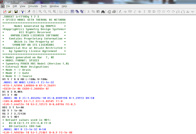
선택을 하게 되면 아래 그림 처럼 spiec model의 내용이 나오게 된다.
그리고 .SUBCKT  로 마우스 커서를 옮긴 후 오른쪽 마우스 버튼을 누르면


아래 그림과 같이 Create Symbol 이 보일 것이다.


"Create Symbol"을 선택 하면 "Do you wish to automatically create a symbol ....."
라는 popup 윈도우 창이 나타날 것이고 "예(yes)"를 선택 하면 다음과 같이 LTspice 모델이 만들어지게 된다. 여기서 이 모델을 사용 하려면 1,2 ,3 pin 무엇으로 되어 있는 지는 알고 있어야 한다.
 위에 나와 있는 것처럼 Node 1 -> Drain , Node2 -> Gate , Node 3 -> Source 이다.


LTspcie 기초

여기서는 설치 방법과 HVAC회로를 재현하는 방법을 기준으로 설명하도록 하겠다.

아래 홈피로 가서  (Window 유저대상)
http://www.linear.com/

Download LTspice IV for Windows 를 선택하면

다음과 같은 window가 보일 것이고 가입을 원하면 가입하면 되지만,
 그냥 다운로드만 한다면 나와 있는 것처럼
No thanks, just download the software를 선택하면 된다.


Basci DC 모터 이해 (FAN)

 여기서 DC motor를 살펴 보는 이유는 간단하다. FAN을 외장형 router에 쓸 예정인 데 구매 하지 않고 구할 수 있었던 팬(An electrical fan)이 컴퓨터 케이스에 달려 있는 것이었고 그 electrical fan 이 DC motor 로 구동된다는 것을 알았기 때문이다.
다음과 같은 방법으로 DC motor 에 대해 찾아보았다.
1. An electrical FAN (선풍기(?))에 붙어 있는 라벨 확인
2. 인터넷으로 해당 fan의 data sheet를 찾는다. --> DC motor 임을 확인
3. simple DC motor circuit 찾아본다.


다음과 같이 simplest circuit으로 모터 control 을 할 수 있는 것이다.
또한 R & L 로 구성됨을 알 수 있었다.
또한 이런 간단한 회로만으로 구성을 하면 switch off 되는 순간 회로에 damage를 줄 수 있는 current가 발생 할 수가 있음을 알 수 있었다. 그러나 모터 자체에서 생길 수 있는 reverse current(switch off시)가 power circuit에 얼마 만큼의 입력 저항 가질 때 문제가 될 지 아직 모르기에 이 부분은 추 후 생각해 봐야 할 부분인 듯 보인다.